Getting Started
In the following, we describe the setup and some basic scan server interactions.
Initial Setup
We assume that you already have a recent version of EPICS base installed with access to commands like softIoc, caget, caput.
Prepare the PyScanClient library and examples:
git clone https://github.com/PythonScanClient/PyScanClient.git
cd PyScanClient
python setup.py build
export PYSCANCLIENT=`pwd`
In here, we don’t “install” the library but simply access it via the python path. In addition to the library, clients also need access to the examples, so we add both to the path used by C-Python:
export PYTHONPATH=$PYSCANCLIENT/build/lib:$PYSCANCLIENT/example
The scan server is a CS-Studio service. Both the scan server and the CS-Studio GUI can be built from https://github.com/ControlSystemStudio/phoebus. More convenient binaries are available from https://controlssoftware.sns.ornl.gov/css_phoebus/nightly/
All CS-Studio tools are implemented in Java. Some CS-Studio GUI binaries bundle a java runtime. If it includes a jdk folder, use that. Otherwise fetch a Java runtime from https://jdk.java.net. Either way, declare your JDK and add its bin folder to the PATH:
export JAVA_HOME=/path/to/jdk
export PATH=$JAVA_HOME/bin:$PATH
java -version
Both the scan server and the CS-Studio GUI likely need to access the same PVs, so you can create a common my_settings.ini for them. In here we start with just localhost:
echo org.phoebus.pv.ca/addr_list=127.0.0.1 >>my_settings.ini
For more on PV related settings, see https://control-system-studio.readthedocs.io/en/latest/preference_properties.html#pv
For the CS-Studio displays, we add the path to this python library and its examples:
echo org.csstudio.display.builder.runtime/python_path=$PYTHONPATH >>my_settings.ini
This …/python_path setting is for CS-Studio displays to locate display scripts. It is not required by the scan server, but for simplicity you may combine settings in a common file loaded by all CS-Studio tools, since the tools will ignore settings that don’t apply to them.
The scan server uses an additional configuration file. For a full example see https://github.com/ControlSystemStudio/phoebus/blob/master/services/scan-server/src/main/resources/examples/scan_config.xml
For these tests we use a simpler file based on this template to primarily set the path used by server-side scripts:
<?xml version="1.0"?>
<scan_config>
   <!-- Path to server-side scripts -->
   <path>to_be_set</path>

   <!-- Simulation information for a PV
        Slew rate is in [units of the device] / second
        The (simulated) neutrons change at about 7/sec
     -->
   <pv>
       <name>neutrons</name>
       <slew_rate>7</slew_rate>
   </pv>
   <!-- Proton charge: About 3.5e12 / hour = 9.7e8 / sec -->
   <pv>
       <name>pcharge</name>
       <slew_rate>9.7222e+08</slew_rate>
   </pv>

   <!-- In addition, a name_pattern (regular expression is supported -->
   <pv>
       <name_pattern>motor_.</name_pattern>
       <slew_rate>10</slew_rate>
   </pv>
</scan_config>
Based on that template, create the file for your PyScanClient example path:
cat $PYSCANCLIENT/example/server/scan_config_template.xml |
sed -e "s#<path>.*#<path>$PYSCANCLIENT/example/server</path>#" >my_scan_config.xml
Assuming you fetched a scan server binary, start the scan server like this:
unzip scan-server.zip
rm scan-server.zip
cd scan-server-*
./scan-server.sh -settings /path/to/my_settings.ini -config /path/to/my_scan_config.xml
On success, note the REST URL and list of console commands:
INFO ... Scan Server (PID 1766187)
INFO ... Scan Server REST interface on http://localhost:4810/index.html
Scan Server Commands:
help            -  Show commands
...
shutdown        -  Stop the scan server
You would stop the scan server by typing shutdown, then restart as just shown.
Test Beamline
Subsequent sections use a test beamline created by simulation.db. The scan GUIs use additional databases. Start them all in one IOC like this:
cd $PYSCANCLIENT/example/ioc
softIoc -m S=Demo -d simulation.db -d table.db -d range.db -d fit.db
Assuming you fetched a binary for CS-Studio, start the associated GUI like this:
unzip phoebus-linux.zip
rm phoebus-linux.zip
cd phoebus-*/
./phoebus.sh -settings /path/to/my_settings.ini -resource $PYSCANCLIENT/example/opi/1_BeamLine.bob

Familiarize yourself with the simulation.
The “Beam” is mostly on, but turns itself off for brief periods.
Click on the “Shutter” to open or close it. While beam is on and the shutter open, the “Neutrons” counter increments. The “Proton Charge” increments as well, but you may only see that when you show it in “Probe” or a “Data Browser”.
Move the “X” and “Y” motor position sliders. There’s a motor position that maximizes the signal on the detector (vertical orange bar).
Move the “Device” setpoint slider and notice how its value (horizontal orange bar) follows with a delay.
Direct REST Access
The scan server is fundamentally a web service. You will typically NOT directly interact with the web service, but point your web browser to http://localhost:4810 and try the following.
You should see a “Scan Server REST Interface” web page. Seeing that page confirms that the scan server is running. In an operational setup you might try to point a web browser on some control system operator interface host to http://name_of_server:4810 to check network connectivity to the scan server.
Follow the “/server/info” link. The XML format of the information is obviously not meant for interactive use. For example, you would have to convert a UNIX epoch start time of “1711118742626” into “2024-03-22 10:45:42 EDT” to verify the scan server start time, but if all else fails such direct REST access can help you to debug your setup on a low level.
Back from the start page http://localhost:4810, click the “/scan/{name-of-new-scan}” link for submitting a new scan. The “Example” scan that is pre-populated in the web interface will set the “xpos” motor to 1, then 2, and log each value.
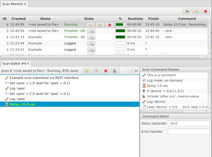
“Submit” the scan and note in the CS-Studio GUI how the X motor is moved. The web interface will indicate the “ID” of the submitted scan and then switch to a list of scans. You may find the submitted scan either already finished or with an active “Delay 10.0 sec” command. Note that the web page needs a manual refresh to update. After a few manual refreshes, the scan should be “Finished”.
On the list of scans, follow the “(cmds)” link to view the commands of the scan, which should match what was submitted. Follow the “(data)” link and note how it lists one sample with value 1.0 and another with value 2.0.
Scan Server Console
In the scan server console, note how it logs each executed command. Type “help”, then “scans”. Type “commands ID” with the ID of the last submitted scan to get a list of commands. Type “data ID” to show the logged data.
Stop the scan server by typing “shutdown” in its console, then restart the scan server. Try “scans” again. Note that “commands ID” will report an error because the list of commands is only held in memory for the duration of a scan server run. On the other hand, “data ID” will still show the logged data, which is persisted over scan server restarts. Those logged values are meant to help debug a scan or track its progress. It is neither meant to replace an archive system or experiment data aquision.
Back from the start page http://localhost:4810, click the “/scan/{name-of-new-scan}” link and submit anoter example scan.
CS-Studio GUI Scan Tools
In CS-Studio, invoke the menu Applications, Scan, Scan Monitor. You should see the last submitted scan as “Finished-OK”, the others as simply “Logged”.
Right-click on any scan and open the “Data Table”.
Right-click on the “Finished” scan and open the “Scan Editor”.
In the scan editor, right-click to “Submit scan”. It submits the same commands once more. While the scan is executing, the scan editor highlights the active command in green. Both the scan monitor and editor offer a red button to abort the scan.

In the scan editor, create a list of “Delay 1 sec” commands by deleting everything else, dragging one “Delay” command from the palette into the editor, then use copy/paste from the context menu or Control-drag-drop to create about 10 delays.
Submit the scan and note how it highlights the active delay command. Use the “pause” button in either the scan monitor or editor to pause and then resume the commands.
Quickly submit the scan multiple times from the scan editor. Use the “Re-submit Scan” entry from the scan monitor context menu. Note how one scan executes, and additional scans queue up to be executed next. Idle scans can be moved up or down in the list of queued scans, or aborted.
In the scan monitor, select a few older scans, right-click on them and “Remove selected”.
The scan monitor is very useful to track the progress of queued and active scans.
The scan editor could be used to manually assemble small scans, but it’s mainly meant to debug scans that have been submitted by other means.
The scan server will hold the commands of past scans in memory and persist the logged data on disk, but this is all meant to debug scans, not to replace data aquisition. Based on memory usage thresholds, the scan server will automatically reduce in-memory scans to logged scans. While the scan monitor can list many scans, reading the list of scans from the server and displaying it in the GUI will use noticable CPU once there are 10000 and more scans in the list. Periodically, for example when a new series of experiments start, it is thus suggested to manually remove older scans, either by deleting selected scans or by invoking “Remove completed scans” from the scan monitor context menu.
Basic PyScanClient
Check the content of example/commands1.py and run it:
cd example
python commands1.py
from scan import *

# Assemble list of commands
cmds = [
    Set('shutter', 1),
    Loop('motor_x', 1, 10, 0.5,
    [
       Comment('daq:start'),
       Delay(10),
       Comment('daq:stop'),
       Log('motor_x')
    ], readback='motor_x', tolerance=0.5)
]

print("Basic list of commands:")
print(cmds)
# Result:
# [Set('shutter', 1), Loop('motor_x', 1, 10, 0.5, [ Comment('daq:start'),...

# Alternatively, use `CommandSequence` which can start
# empty or use list of commands
seq = CommandSequence(cmds)
# Commands can be added to sequence
seq.append(Comment('Done'))

print("`CommandSequence` results in nicer printout:")
print(seq)
# Result:
# [
#     Set('shutter', 1)
#     Loop('motor_x', 1, 10, 0.5,
#     [
#         Comment('daq:start'),
#         Delay(10),
#         Comment('daq:stop'),
#         Log('motor_x')
#     ], readback='motor_x', tolerance=0.5)
#     Comment('Done')
# ]

# .. and then submit to scan server for execution
client = ScanClient()
id = client.submit(seq)
Note how the python script assembles a list of commands. It builds the recipe, submits it to the scan server, and exits. The scan server then spends more than a minute to execute the submitted commands.
In the CS-Studio scan monitor, right-click on the running scan to open the “Scan Data Table” and watch how samples are added. This internal data logger is again not meant to replace data aquisition, but assists in tracking the progress of scans.
At this point you may familiarize yourself with all the scan commands,
especially the many options of the Set command.
The PyScanClient tutorial folder contains several more example scripts.
Default Device Settings
The command to set a power supply voltage may be instantaneous:
commands = [ Set('PS42:Voltage', 12.0),
             Comment("PS is now on at 12 Volts") ]
But this device behavior tends to be the exception. When controlling a motor, the EPICS motor support allows a “put-callback” to the device which waits until the motor reaches the desired location. This mechanism is also referred to as “completion”. A temperature controller might support completion on its temperature setpoint PV. On devices that do not support completion, it may be possible to read the current device state from a separate readback PV and wait until it agrees with the commanded value.
Based on the device at hand, we want to use the appropriate Set command:
Set('SomePV', 42.3, completion=True, timeout=30)
Set('SomePV', 42.3, completion=True, timeout=3000)
Set('SomePV', 42.3, completion=True, timeout=3000, readback="SomePV.RBV", tolerance=0.1)
Set('SomePV', 42.3, readback="OtherPV", tolerance=10, timeout=15)
Unfortunately, the “correct” way to set a PV is not discernible from the outside. It requires knowledge about the implementation of a PV in the IOC. And even if the correct way to set a PV is known, having to type all parameters for each Set command can be cumbersone. The PyScanClient scan settings provide a way to configure default parameters for each PV. Wrappers for the basic Set, Loop and Wait commands then use these defaults. For an example, see example/beamline_setup.py:
"""Example for beamline specific setup
   All scripts that access the scan server should start with

     'from beamline_setup import *'
"""

# Get all scan commands
from scan import *
# Replace basic Loop/Set/Wait commands with wrappers that use scan settings
from scan.util import SettingsBasedLoop as Loop
from scan.util import SettingsBasedSet as Set
from scan.util import SettingsBasedWait as Wait

# Implement ScanSettings for this beamline
class BeamlineScanSettings(ScanSettings):
    def __init__(self):
        super(BeamlineScanSettings, self).__init__()

        # Define settings based on PV name patterns (regular expressions).
        # Order matters! List patterns first, specific PVs last.
        # In general, motors should use completion, and check a readback
        self.defineDeviceClass("motor_.", completion=True, readback=True)
        # The specific motors in the simulation.db, however, don't support completion
        self.defineDeviceClass("motor_x", completion=False, readback=False)
        self.defineDeviceClass("motor_y", completion=False, readback=False)
        self.defineDeviceClass("shutter", readback=True)
        # The simulated "setpoint" uses a different "readback" PV as its readback.
        # readback=False skips readback check
        # readback=True calls getReadbackName(pv) which typically returns the PV itself
        # readback='whatever' uses provided PV
        self.defineDeviceClass("setpoint", completion=False, readback="readback", tolerance=0.1, timeout=20)
        # When waiting for proton charge or neutron counts, use "increase by"
        self.defineDeviceClass("pcharge", comparison="increase by")
        self.defineDeviceClass("neutrons", comparison="increase by")

        # Each site may add more to its site-specific configuration.
        # The example/opi for alignment uses these to populate drop-downs
        self.settable = [ "motor_x", "motor_y" ]
        self.waitable = [ "seconds", "time", "pcharge" ]
        self.loggable = [ "signal" ]

    def getReadbackName(self, device_name):
        # Anything that looks like a motor very likely has a .RBV.
        # But that does not apply to the simulated motor_x, motor_y
        if device_name in ( 'motor_x', 'motor_y' ):
            return device_name
        if "motor" in device_name:
           return device_name + ".RBV"

# Install beam line specific scan settings
scan_settings = BeamlineScanSettings()
setScanSettings(scan_settings)

# 'Meta Commands'
def Pre():
    return Set('shutter', 1)
def Post():
    return Set('shutter', 0)

def Start():
    """Start data acquisition"""
    return Sequence( Set('loc://daq_reset(0)', 1),
                     Set('loc://daq(0)', 1)
                   )

def Stop():
    """Stop data acquisition"""
    return Set('loc://daq(0)', 0)

def TakeData(counter, limit):
    return  Sequence(Start(), Wait(counter, limit), Stop())

def SetChopper(wavelength, phase):
    return  Sequence(Set('loc://chopper:run(0)', 0),
                     Set('loc://chopper:wlen(0)', wavelength),
                     Set('loc://chopper:phs(0)', phase),
                     Set('loc://chopper:run(0)', 1)
                    )

def table_scan(headers, rows):
    """Create table scan with pre/post/start/stop for this beam line"""
    table = TableScan(headers, rows,
                      pre=Pre(),
                      post=Post(),
                      start=Start(),
                      stop=Stop())
    return table.createScan()

# Shortcut
ndim = createNDimScan

# Create a scan client, using the host name that executes the scan server
scan_client = ScanClient('localhost')

# As a convenience, `python beamline_setup.py` prints settings
if __name__ == '__main__':
    from scan.util.scan_settings import getScanSettings

    print("Beam Line scan settings")
    print("=======================")
    for setting in getScanSettings().device_settings:
        print(setting)
    print("")
    print("Scan Client")
    print("===========")
    print(scan_client)
The code in example/beamline1.py, example/beamline2.py and example/beamline3.py shows how to take advantage of the scan settings.
CS-Studio GUI combined with PyScanClient
End users can assemble recipes for a scan by writing python scripts similar to the ones shown so far. In practice, however, it is more likely for experts to prepare such scripts. End users then adjust key parameters and execute the script.
For frequently used recipes, a GUI can be added. Instead of editing a script and executing it in a terminal window, users can then set parameters and submit a scan from the GUI.
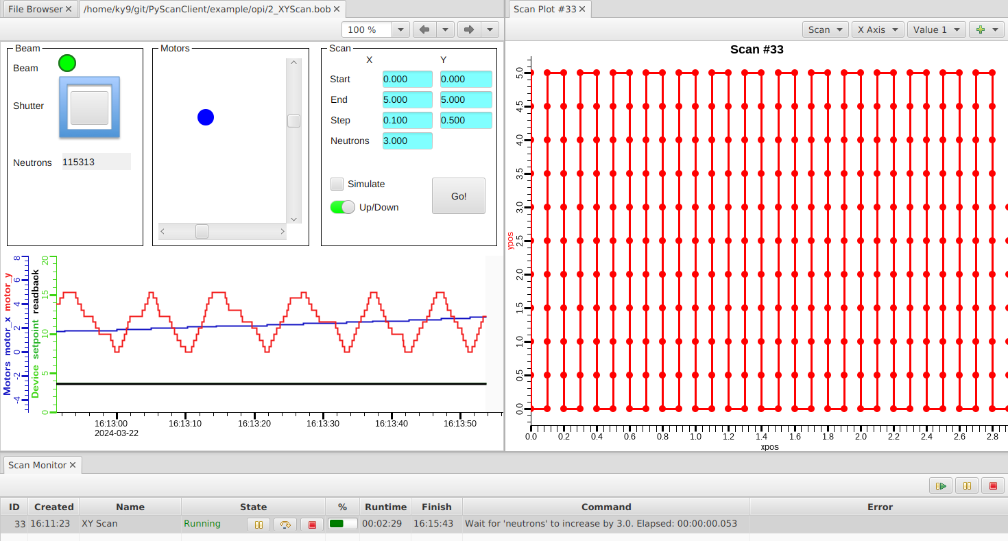
In CS-Studio, use the menu File, Open to open PyScanClient/example/opi/2_XYScan.bob. In addition to the beam, shutter and X/Y motors that we’ve already seen, it adds a “Scan” section. By default, it will scan both motors from 0 to 5, awaiting 3 neutrons at each position.
Press “Go!” and note how the Scan Monitor now shows a running “XY Scan”. Right-click on the scan in the monitor, open the “Scan Data Table” and watch it grow by a row for each scanned position. Close the data table and instead open the “Scan Data Plot”. From the “X Axis” drop-down, select “motor_x”, and from the “Value 1” drop-down select “motor_y”.

Start the next scan after “Up/Down” is turned off and compare the motor positions in the plot.
Check “Simulate” to submit the scan for simulation, without actually executing it. Simulation can be useful to verify which commands will be created. It performs a simple run time estimate based on rate-of-change estimates that need to be configured on the scan server.
To see how this is implemented, open the display in the CS-Studio display editor. In this example, all scan parameters use local PVs. If you prefer to persist the parameters when the display is closed and later re-opened, you would use real PVs. Pushing the “Go!” button executes example/opi/scripts/xy_scan.py:
"""Script for GUI that builds and submits scan"""

from org.csstudio.display.builder.runtime.script import ScriptUtil, ValueUtil
from java.lang import Runnable
from javafx.application import Platform
from org.csstudio.scan.info import SimulationResult
from org.phoebus.framework.workbench import ApplicationService
from scan.commands.loop import Loop
from scan.commands.wait import Wait
from scan.commands.log import Log
from scan.client import ScanClient

# Fetch parameters from display
x0 = ValueUtil.getDouble(ScriptUtil.getWidgetValueByName(widget, "x0"))
x1 = ValueUtil.getDouble(ScriptUtil.getWidgetValueByName(widget, "x1"))
dx = ValueUtil.getDouble(ScriptUtil.getWidgetValueByName(widget, "dx"))
y0 = ValueUtil.getDouble(ScriptUtil.getWidgetValueByName(widget, "y0"))
y1 = ValueUtil.getDouble(ScriptUtil.getWidgetValueByName(widget, "y1"))
dy = ValueUtil.getDouble(ScriptUtil.getWidgetValueByName(widget, "dy"))
neutrons = ValueUtil.getDouble(ScriptUtil.getWidgetValueByName(widget, "neutrons"))
simu = ValueUtil.getInt(ScriptUtil.getWidgetValueByName(widget, "simu")) > 0
if ValueUtil.getInt(ScriptUtil.getWidgetValueByName(widget, "updown")) > 0:
    toggle = -1
else:
    toggle = 1

# Create scan
cmds =[
  Loop('motor_x', min(x0, x1), max(x0, x1), max(0.1, abs(dx)),
    Loop('motor_y', min(y0, y1), max(y0, y1), toggle * max(0.1, abs(dy)),
    [
        Wait('neutrons', neutrons, comparison='increase by'),
        Log('motor_x', 'motor_y', 'readback')
    ]
    )
  )
]

if simu:
    sim = ScanClient().simulate(cmds)

    class ShowSimulation(Runnable):
        def __init__(self, result):
            self.result = SimulationResult(result['seconds'], result['simulation'])
        def run(self):
            inst = ApplicationService.createInstance("scan_simulation")
            inst.show(self.result)

    Platform.runLater(ShowSimulation(sim))
else:
    # Submit scan
    scan_id = ScanClient().submit(cmds, "XY Scan")
This script executes within the GUI with access to the widgets in the display. It is handled by Jython and can use the PyScanClient the same way as C-Python running outside the GUI.
Table Scan
Scans that need to set devices like motors to a list of desired positions, start data acquisition at each point, wait for some condition, stop data acquisition, and then move to the next point can often be expressed in a concise table notation.
In CS-Studio, use the menu File, Open to open PyScanClient/example/opi/3_Table_Scan.bob. Push the file folder button next to the “Table:____” text field to locate the file PyScanClient/example/tablescan.csv. Press “Load” and “Submit”.

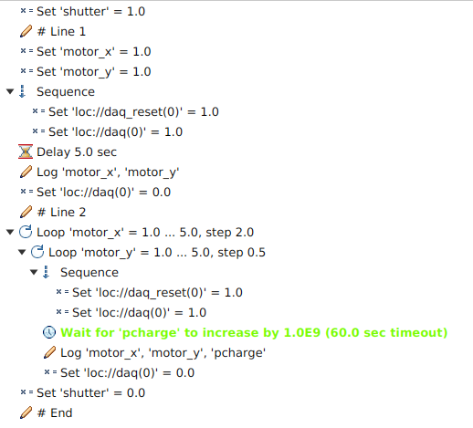
In short, table columns are typically PV names, and cells contain their values. Cell values for PVs may contain plain values as in the first row which sets both motors to 1. Cells may also contain lists of values or loop(start, end, step) constructs, as in the second row which will create nested loops setting motor_x to 1, 3, 5, while an inner loop will set motor_y to 1, 1.5, 2, …, 4.5, 5.0.
The triplet of columns “Wait For”, “Value” and “Or Time” has special meaning. In the first row, after setting the motor positions, we wait for 5 seconds. In the second, we wait for the proton charge to increment by 1e9, or move on after 1 minute, whichever comes first. Either way, the Start() commands which presumably start data aquisition are executed just before we wait, and the Stop() commands which close data aquisition are executed after each “Wait For”. Each PV that is used in a table row is logged at the end of each row.
Finally, the list of commands created for a table scan start with Pre() commands and end with Post() commands. In the beamline_setup.py shown above those are used to open and then close the shutter. The resulting list of commands can be checked by opening the submitted scan in the scan editor:

See scan.table.table_scan for more on the table syntax.
The PyScanClient fundamentally supports table scans in CSV format. The CS-Studio GUI offers a basic table display where values can be adjusted before submitting. Most spreadsheet programs can be used to create or edit more extensive table scans, which are then exported as CSV to load and submit them from the GUI. You may also extend your local copy of the tablescan GUI scripts to call out to tools like the LibreOffice file converter, “soffice –convert-to csv …”, which then allows the GUI to directly load such spreadsheet files without manual conversion to CSV.
Alignment Scan
One fairly common beamline procedure is an alignment. For example, a slit or sample is moved across a range of positions, the intensity of a signal is noted at each position, and we try to locate the maximum of that signal.
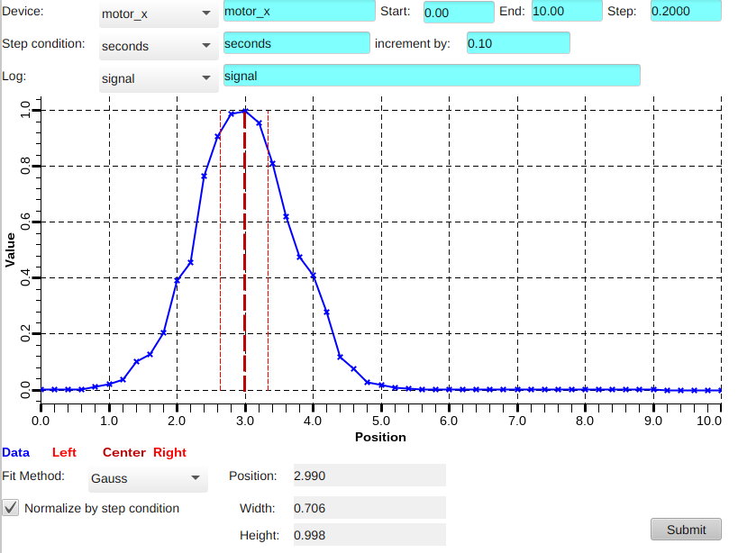
In CS-Studio, use the menu File, Open to open PyScanClient/example/opi/1_BeamLine.bob and in there set the “Y” motor to 3.0. Now open PyScanClient/example/opi/4_Alignment_Scan.bob. Adjust the settings as shown in the following screenshot, then press “Submit”. The GUI submits commands for moving the X motor over a range of positions. At each step we wait for some time, then log the motor position and some signal. Finally, a gaussian fit is performed to locate the peak in that signal.

When inspecting the submitted commands by opening them from the scan monitor into the scan editor, the commands for moving the motor and logging the signal are quite straight forward. In addition, there are “script” commands.

Script commands can invoke jython code within the scan server. These scripts have access to PVs and to the logged data of a scan. In this alignment scan, a “WriteDataToPV” script command is invoked to write data from the logged “motor_x” and the logged “signal” into waveform PVs. Those waveform PVs are then shown in the display to track the progress of the scan. Finally, a “FindPeak” command is used to locate the peak in the logged data and to publish the result via PVs.
For more on the Script command, check its documentation in the
list of scan commands.
For implementation details of these specific custom scripts,
look for writedatatopv.py and findpeak.py in the PyScanClient/example/server folder.
Note that this example not only introduces script commands but also stretches their purpose. The jython code of a script command has access to most of the scan server. It can implement functionality that is not offered by the basic scan commands. This is both an opportunity and a risk. The use of script commands should remain limited. Each script command needs to be well tested to assert that it is not impacting the robustness of the scan server.
For this specific example of an alignment scan, a better solution is the implementation of an alignment IOC. This may be done in python, using a python channel access or PV access server library. Such an alignment IOC has PVs similar to those shown in this alignment display to configure which PVs to “move”, how to wait at each step, and what signal to log. Implementing such an alignment IOC in python opens up access to many types of peak fitting algorithms. The alignment IOC should have an option to end with positioning the moved motor at the peak of the signal. Finally, the alignment IOC should expose a “Run” PV which supports put-callback.
Such an alignment can then be invoked interactively from a GUI, but it can also be configured and started from a scan, for example a table scan which configures the alignment PVs and then writes to the “Run” PV, using completion.
Production Setup Notes
In the above example we executed the scan server within a terminal window. A production setup would typically run it as a Linux service using procServ, https://github.com/ralphlange/procServ
Both the scan server and the CS-Studio GUI are typically started by a site-specific launcher script that adds -settings /path/to/my_settings.ini.
By default, the scan server log is stored in the /tmp folder. In the scan_config.xml, it should be configured to be in a more permanent location.
The scan config file can also list “pre” and “post” commands that are always executed at the start and end of each scan. Specifically, the “post” commands are executed both when a scan completes successfully and when it fails.
